Diwheel: A two wheeled, pedal powered vehicle
Creative Fields
Engineering
Course or Client
ENGS 146 Computer Aided Mechanical Design
Completion Date
Spring 2015
Skills
SolidWorks Professional Certification Mechanical Design
SolidWorks Simulation Tools Machining
TIG Welding Milling, Lathing
Challenge: To design, build and race a pedal-powered diwheel as the culminating project for Computer Aided Mechanical Design.
 SolidWorks Photoview 360 Render |
|---|
 The Team |
 Differential and Drive Wheels |
 Differential Design |
 Thayer Instagram |
 Differential Stack Up |
 The Diwheel |
Winner of the 2015 ENGS 146 Diwheel Competition
Received the Best Fits and Finishes Award
The Bevel is in the Details
Team: Bevel's Advocate
With head-turning styling, seamlessly smooth acceleration, and that indescribable, but incredibly potent diwheel allure, the Bevel’s Advocate is one of the most desirable diwsheel rides on the market. At an applied rider torque of 26 lb-ft, converting to 5.5 lb-ft[2] on each wheel, this diwheel accelerates from 0 to 5 mph in under 10 seconds. Helping to make Bevel’s Advocate’s sublime driving dynamics possible is a rigid, open chassis that features advanced hardened steel and Thayer machine shop manufacturing and welding techniques. The suspension is derived from hoop spring between the offset drive wheel several inches above the center of mass and the front guide wheel, and the custom made rear differential maintains smooth turning for tight maneuverability. Standard aluminum bike brakes are effective at bringing the Bevel’s Advocate down from extreme diwheel speeds, and the anti-gerbilling mechanisms provide both stylistic additions as well balance and over-correction protection.
Sporting a 135° reclined rider angle, and optimized for riders from 5’2” to 6’4” Bevel’s Advocate is balanced at equilibrium with and without a rider. At 31.5” in width this diwheel has a 0° turning radius. With four speed shifting, acceleration at the start line is smooth, and avoids unnecessary torqueing on the drive mechanism by allowing the rider to build momentum and speed as they shift into higher gears, instead of always starting in their race gear.
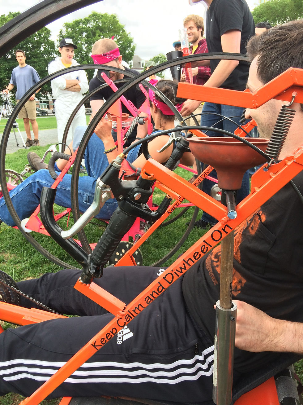
Above | Competion Day
 |
|---|
 |
 |
 |
 |
 |
 |
 |
 |
My Contribution
I flourish working on teams. I am often looked to as a leader and creative influence, but I am a team player at heart and often support my teammates to develop their own leadership. On this project I was the point person for project management and making sure my team finished several days ahead of the other teams, so that we could test, break and fix any weakness in our design before competition day. I designed, prototyped and built the steering and braking system. I MIG welded the chassis frame, and built welding jigs for prcise alignment, especially of the drive and differential system. I co-designed our differential and came up with wild ideas to push our team to think beyond prior art.
Check out our final report for
-
SolidWorks simulation studies
-
Engineering drawings
-
Bill of materials
-
Detailed descriptions of key assemblies
-
Manufacturing & assembly
Manufacturing & Assembly
Pictorally.
 Bike DemolishTeams were limited to 2 bikes for parts. |  Center of Mass CalculationBalance is essential to optimize speed and agility in the competition. We calculated the center of mass and distributed the weight of the diwheel to ensure balance. |
|---|---|
 Checking for bearing frictionUsing a machinist stethoscope to listen to the bearings. A poorly oiled bearing makes a rattling sound. |  Team frame weldingEach piece was hand cut, edges were angled and sanded. Welding locations were sanded to uncover non-oxidized steel. |
 Interior of the differentialFour bevel gears surround a central "spider block" for stability. Bushings in our original design were substituted for bearings later on to increase performance. |  Checking the level for precisionPrecise alignment of the drive axle would lead to significantly less friction in bearings and allow for smooth operation of the differential. |
 Adjusting the Drive JigA rigid aluminum bar was used to vertically align the drive axle. |  Hilary welding gussetsGussets were implemented after SolidWorks simulation analysis of the frame showed where added rigidity was needed. |
 Welded Drive ConnectionsSteel, plasma cut connectors. Modular design keeps manufacture easy. |  Welding Jig for Axle AlignmentThe aluminum piece was designed to align the corners of the steel pieces with the shaft collar as well as determine the space between the two planar steel pieces. |
 Stylistic Additions to the DiffTeam name and logo laser engraved on acrylic casing for the differential. |
Videos
| Differential in motion. | Plasma cutter making gussets. | Maneuverability testing.
Competition Day

Above | ENGS 146 Class | Spring 2015 on competition day. Bevel's Advocate in black with orange accents.
Below | Left, the team with Professor Diamond. Center, Silas making the final turn. Right, Diwheel preparing for the plunger challenge.


